GENERAL GRP PIPE AND FITTING SPECIFICATIONS
The GRP pipes and fittings are constructed from resin and glass fiber reinforcement combined with additives to form a composite structure to satisfy the performance requirements of these specifications. The pipes and fittings are designed to achieve a minimum working life of 50 years under all applicable loading, environmental and installation conditions. Pipes can be produced using an unrestrained joint or using a restrained joint where no thrust blocks are used at the change of directions. All pipes and fittings have a minimum initial specific stiffness – determined in accordance with ASTM D 2412 – or ISO 7685 of 5000 N/m2 for burial depths up to 10 m and 10000 N/m2 for greater depths. A stiffness of 2500 N/m2 could be used for burial depth up to 4 m depending on the native soil and the backfill. All pipes and fittings are capable of withstanding the working pressures, test pressures and loading mentioned in the specifications. The pipes and fittings are designed to withstand up to 5% long term deflection in their installed conditions. Pipes will have a 50 year strain corrosion design value as per ASTM D3262 section 6.3.1 latest edition for sewer pipes. Representative samples from production will pass the strain corrosion control requirements of ASTM D3262 section 6.3.2 for the 100 and 1000 hour test. 1. Applicable Standards
2. Manufacture 3. Resin No pigments are added. All resins used have been tested in accordance with the resin manufacturer’s specification for viscosity and reactivity performance. All resin systems are at least equal to the requirements of BS 3532 - type B. 4. Glass The reinforcements comply with the standards listed below as appropriate.
5. Pipe Liner
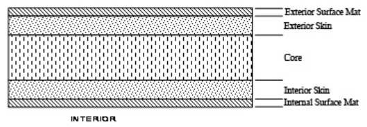
6. Pipe Structure The pipe is a corrosion resistant composite laminate consisting of polyester resin, Fiberglas filament winding, Fiberglas chopped roving (if applicable), surfacing veil and finely graded sand (applicable for the larger diameters). The laminate has a central core with high content of sand to give the pipe its rigidity and stiffness.
7. Dimensions and Tolerances Dimensions and Tolerance conform to the recommendations of the ISO 10467 and ISO 10639.
8. Fittings All fittings such as bends, tees, junctions, reducers and the like conform to ISO 10467. The construction or bends are swept or mitered as designed. Laminated joints used in the fabrication of fittings are equal or superior in strength to the sections they join.
9. Flanges GRP flanges are flat faced and drilled to BS. 4504 PN 10 or PN16 drilling pattern. Flanges are filament wound or contact molded. GRP Flange gasket are of a design, material and thickness as recommended by the GRP fitting manufacturer.
10. Joints (for buried pipes) Except where otherwise detailed on the drawings, all pipes and fittings have joints. Joints of GRP coupling , Butt and Wrap type or Key-Lock.
11. Aggregates and Fillers Additives if used are from 98% pure silica sand as defined in BS-5480 1990 and AWWA C-950 and do not contain impurities. The aggregates are used in the stiffening layer of the pipe wall. GRP pipe specifications are based on the performance requirements specified in the relevant ASTM and AWWA standards. The piping systems do not necessarily conform to the pressure classes and dimensions given in these standards. The applicable standards are:
The general pipe wall structure is depicted in Figure 2 |
 |